Medal For Excellence

Medal For Excellence

Friday, August 31, 2012

Sijil Kemahiran Malaysia (SKM)


Sijil Kemahiran Malaysia ( SKM )

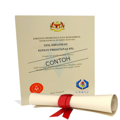
Persijilan Kemahiran Malaysia merupakan salah satu fungsi utama Jabatan Pembangunan Kemahiran (JPK). Persijilan ini menawarkan lima (5) tahap persijilan iaitu :

 Sijil Kemahiran Malaysia (SKM) Tahap 1
 Sijil Kemahiran Malaysia (SKM) Tahap 2     
 Sijil Kemahiran Malaysia (SKM) Tahap 3
 Diploma Kemahiran Malaysia (DKM) Tahap 4
 Diploma Lanjutan Kemahiran Malaysia (DLKM) Tahap 5
Persijilan Kemahiran Malaysia boleh didapati melalui tiga (3) kaedah:

1. Melalui Latihan di Institusi yang Diiktiraf
Kaedah melalui program latihan kemahiran di pusat-pusat bertauliah JPK bagi bidang & tahap kemahiran yang tertentu dan telah ditauliahkan.

Contoh: Kolej Despark Auto (Pusat Bertauliah) menawarkan kemahiran dalam sektor kemahiran Teknologi Automotif Tahap 1, 2 & 3.
Para pelatih akan diajar kemahiran membaiki dan menservis kenderaan (70%) dan diajar teori operasi sistem serta komponen bagi sesebuah kereta (30%).
Kemudahan dan teknologi terkini disediakan bagi meningkatkan lagi kemahiran para pelatih mengikut peredaran semasa teknologi automotif.


2. Melalui Latihan Berorientasikan Industri (SLDN)
Kaedah latihan perantisan dalam Sistem Latihan Dual Nasional (SLDN) yang dijalankan di industri dan institut latihan kemahiran.

3. Melalui Pentauliahan Pencapaian Terdahulu (PPT)Kaedah mendapatkan Persijilan Kemahiran Malaysia melalui pengalaman lalu (kerja atau latihan) tanpa perlu menduduki ujian.
Calon dikehendaki mengemukakan bukti-bukti ketrampilan yang telah dimiliki untuk dinilai oleh Pegawai Penilai dan disahkan oleh Pengawai Pengesah Luaran yang dilantik JPK.

Faedah Persijilan Kemahiran Malaysia
 Persijilan Kemahiran diiktiraf oleh industri di Malaysia
 Persijilan Kemahiran Malaysia menyediakan suatu laluan kerjaya dan pembangunan diri yang menarik setanding dengan laluan kerjaya berasaskan kelayakan akademik.
 Persijilan Kemahiran Malaysia berupaya melahirkan pekerja mahir yang terlatih dan berkelayakan untuk mempertingkatkan daya saing industri tempatan di pasaran dunia.

Syarat Kelayakan Menyertai Persijilan Kemahiran Malaysia
Syarat minimum menyertai latihan Persijilan Kemahiran Malaysia Kaedah Pertauliahan melalui Institusi Latihan yang diiktiraf, calon-calon mestilah :

 Boleh bertutur dan menulis dalam Bahasa Melayu atau Bahasa Inggeris
 Mempunyai SKM tahap yang lebih rendah untuk menyertai SKM tahap yang lebih tinggi dalam bidang kursus yang sama.
(* Walau bagaimanapun, Pusat Bertauliah boleh menetapkan lain-lain syarat kepada pelatih-pelatih mereka)

Pusat Bertauliah Persijilan Kemahiran Malaysia
Pusat Bertauliah bererti penyedia latihan kemahiran yang telah diluluskan oleh  JPK untuk mengendali latihan kemahiran dan menawarkan Persijilan Kemahiran Malaysia bagi bidang dan tahap kemahiran tertentu berdasarkan Standard Kemahiran Pekerjaan Kebangsaan (NOSS).Terdapat 5 kategori Pusat Bertauliah, iaitu:-
  • Pusat Bertauliah Awam (K)
  • Pusat Bertauliah Swasta (L)
  • Pusat Bertauliah Industri (I)
  • Pusat Bertauliah Persatuan (P)
  • Pusat Bertauliah Ujian Tanpa Musnah (NDT)


Thursday, August 30, 2012

KERETA MERDEKA PERTAMA


Tunku menaiki sebuah kereta berwarna hitam, tidak berbumbung, bernombor plet : M 4442. Kereta ini dipinjam oleh Encik Gaffar Baba daripada seorang tauke cina di Melaka.

Usaha menjejaki kereta klasik model Nash Rambler Custom Covertible 1951 seperti yang digunakan Perdana Menteri pertama,Tunku Abdul Rahman Putra Al-Haj, ketika pengisytiharan tarikh kemerdekaan Persekutuan Tanah Melayu di Padang Banda Hilir, Melaka, 20 Februari 1956, berhasil apabila kereta itu ditemui di Ohio, Amerika Syarikat (AS).

Kereta bernilai RM171,000 itu kemudian dibeli daripada syarikat Motocar Portfolio di Ohio, AS, menerusi ejen Bumiputera yang dilantik, Faroib Enterprise Sdn Bhd dengan kerjasama Arkib Negara Malaysia (ANM), yang menjejakinya sejak awal bulan lalu.

Kereta itu dibawa menerusi penerbangan kargo Federal Express dan mengambil masa selama 17 hari bermula dari tarikh pengesahan pembelian di pusat jualan di Ohio, (AS), sebelum singgah di perhentian terakhir di Subic Bay, Filipina, kelmarin.

Kereta itu akan digunakan pada perarakan konvoi kemerdekaan ke-50 bermula di Lapangan Terbang Batu Berendam ke Dataran Pahlawan di Melaka Jumaat ini dan dinaiki Perdana Menteri, Datuk Seri Abdullah Ahmad Badawi; Ketua Menteri Melaka, Datuk Seri Mohd Ali Rustam Menteri Kebudayaan, Kesenian dan Warisan, Datuk Seri Dr Rais Yatim, bagi mengimbau kembali detik-detik bersejarah itu.

Dr Rais berkata, pada awalnya usaha mendapatkan kereta itu menghadapi pelbagai kesukaran berikutan syarikat terbabit tidak bersetuju menjual kereta terbabit kerana pernah digunakan dalam filem Superman dan menjadi rebutan banyak pihak.

“Namun, selepas rundingan dibuat, syarikat terbabit bersetuju menjualnya. Bagaimanapun, kami masih menghadapi kesukaran membawa pulang kereta terbabit termasuk mendapatkan kelulusan Kastam di Amerika, pesawat yang sesuai untuk membawa dan soal teknikal.

“Sepanjang tempoh itu juga kereta terbabit turut melalui pelbagai proses pengesahan dokumen di Detroit, Chicago Anchorage (Alaska) dan Tokyo, Jepun bagi urusan pengesahan dokumen pembelian dan pemeriksaan Kastam,” katanya pada sidang media selepas menyaksikan ketibaan kereta terbabit di MASkargo di sini, semalam.

Hadir sama Ketua Setiausaha kementeriannya, Datuk Zakiah Ahmad dan Ketua Pengarah Arkib Negara, Sidek Jamil.

Selain itu, Dr Rais berkata, kereta terbabit juga akan melalui beberapa proses penyelenggaraan menyeluruh bagi memastikannya dalam keadaan sempurna ketika digunakan, termasuk mengecat semula kereta itu daripada hijau kepada warna asal pada 1956 iaitu hitam.

Ditanya mengenai harganya yang begitu mahal, Dr Rais berkata langkah membawa kereta itu adalah tepat bagi mengimbau kembali peristiwa bersejarah itu.

“Nilai warisan tidak ada harganya, Malaysia sudah memberi pelbagai kecemerlangan kepada kita.

“Apalah sangat nilai RM171,000 itu, jika dibandingkan usaha mengingati kembali rentetan sejarah yang memberi kebanggaan kepada kita dalam mengingati kepayahan pemimpin terdulu mencapai kemerdekaan,” katanya.

Kereta klasik yang dinamakan sebagai ‘Kereta Merdeka’ kali ini akan menggunakan nombor pendaftaran M4442 iaitu nombor yang sama dengan kereta yang dinaiki Tunku Abdul Rahman ketika itu.

Wednesday, August 29, 2012

Bosch Automotive History 1902

1902

Delivery of the first high-voltage magneto ignition system with Bosch spark plugs.The first high-voltage magneto ignition system with Bosch spark plugs was delivered to Daimler-Motoren-Gesellschaft in 1902. The previous year, Robert Bosch had asked his development engineer Gottlob Honold to improve the design of the low-voltage magneto ignition device so that it could do without its break-spark rodding, a high-maintenance component prone to breakdowns. Robert Bosch was very impressed when, in the same year, Gottlob Honold presented his first prototypes with spark plugs in place of break-spark rodding.


Bosch Automotive History 1897

1897

First successful installation of the Bosch low-voltage magneto ignition device in a motor vehicle.


Robert Bosch and his associate Arnold Zähringer successfully equipped a motor vehicle, a De Dion-Bouton three-wheeler, with a low-voltage magneto ignition device for the first time. Zähringer had an ingenious idea. He decided that the heavy armature did not have to oscillate at all. Instead, he assigned this task to a new part – a light and slender sleeve. This allowed the magneto ignition device to function at high speeds.

Rotary Engine


Like a piston engine, the rotary engine uses the pressure created when a combination of air and fuel is burned. In a piston engine, that pressure is contained in the cylinders and forces pistons to move back and forth. The connecting rods and crankshaft convert the reciprocating motion of the pistons into rotational motion that can be used to power a car.
In a rotary engine, the pressure of combustion is contained in a chamber formed by part of the housing and sealed in by one face of the triangular rotor, which is what the engine uses instead of pistons.
The rotor follows a path that looks like something you'd create with a Spirograph. This path keeps each of the three peaks of the rotor in contact with the housing, creating three separate volumes of gas. As the rotor moves around the chamber, each of the three volumes of gas alternately expands and contracts. It is this expansion and contraction that draws air and fuel into the engine, compresses it and makes useful power as the gases expand, and then expels the exhaust.

The Parts of a Rotary Engine

A rotary engine has an ignition system and a fuel-delivery system that are similar to the ones on piston engines. If you've never seen the inside of a rotary engine, be prepared for a surprise, because you won't recognize much.
Rotor
The rotor has three convex faces, each of which acts like a piston. Each face of the rotor has a pocket in it, which increases the displacement of the engine, allowing more space for air/fuel mixture.
At the apex of each face is a metal blade that forms a seal to the outside of the combustion chamber. There are also metal rings on each side of the rotor that seal to the sides of the combustion chamber.
The rotor has a set of internal gear teeth cut into the center of one side. These teeth mate with a gear that is fixed to the housing. This gear mating determines the path and direction the rotor takes through the housing.
Housing
The housing is roughly oval in shape (it's actually anepitrochoid -- check out this Java demonstration of how the shape is derived). The shape of the combustion chamber is designed so that the three tips of the rotor will always stay in contact with the wall of the chamber, forming three sealed volumes of gas.
Each part of the housing is dedicated to one part of the combustion process. The four sections are:
  • Intake
  • Compression
  • Combustion
  • Exhaust
The intake and exhaust ports are located in the housing. There are no valves in these ports. The exhaust port connects directly to the exhaust, and the intake port connects directly to the throttle.

The output shaft
(Note the eccentric lobes.)
Output Shaft
The output shaft has round lobes mounted eccentrically, meaning that they are offset from the centerline of the shaft. Each rotor fits over one of these lobes. The lobe acts sort of like the crankshaft in a piston engine. As the rotor follows its path around the housing, it pushes on the lobes. Since the lobes are mounted eccentric to the output shaft, the force that the rotor applies to the lobes creates torque in the shaft, causing it to spin.

Tuesday, August 28, 2012

Electrical Chart


Ohm's Law


Say that you’re wiring a circuit. You know the amount of current that the component can withstand without blowing up and how much voltage the power source applies. So you have to come up with an amount of resistance that keeps the current below the blowing-up level.
In the early 1800s, George Ohm published an equation called Ohm’s Law that allows you to make this calculation. Ohm’s Law states that the voltage equals current multiplied by resistance, or in standard mathematical notation.
V = I x R
you can rearrange its elements so that if you know any two of the three values in the equation, you can calculate the third. So, here’s how you calculate current: current equals voltage divided by resistance, or
I = V/R
You can also rearrange Ohm’s Law so that you can calculate resistance if you know voltage and current. So, resistance equals voltage divided by current, or
R = V/I
For example using a circuit with a 10-volt battery and a light bulb (basically, a big flashlight). Before installing the battery,you measure the resistance of the circuit with a multimeter and find that it’s 100ohms. Here’s the formula to calculate the current:
I = V/R =  10 volts/100 ohms =0.1 amps (or100mA)

Ohm's Law

The VIR triangle

You can use the VIR triangle to help you remember the three versions of Ohm's Law.Write down V, I and R in a triangle like the one in the yellow box on the right.

Ohm's Law Triangle
  • To calculate voltage, V: put your finger over V,this leaves you with I R, so the equation is V = I × R
  • To calculate current, I: put your finger over I,this leaves you with V over R, so the equation is I = V/R
  • To calculate resistance, R: put your finger over R,this leaves you with V over I, so the equation is R = V/I

    Understanding Electrical Power

    Electrical power is what drives a motor or produces sound through speakers or provides light through a light bulb. The current alone can not produce energy as the current is the movement of electrons and when the voltage is absent (V=0) current is static (in fact it does not exist). On the other hand voltage alone without current is static and can not be beneficial for driving electrical appliances, actually a million volts static voltage won't harm you. Hence power is directly proportional to both current (I) and voltage (V) of a circuit. It is inversely proportional to the impedance (resistance) (R) of the circuit. For DC circuits, power can be calculated as follows:
    P = V x I
    or
     P = V2/R
    or
    P = Ix R

Monday, August 27, 2012

Evolution of the Ferrari


Hot Import Night Penang (PISA)


The catalytic converter is made of an aluminum oxide honeycomb coated with platinum and palladium. These components react to remove CO and HC's from the exhaust stream. A two-way catalytic converter works by oxidizing CO (carbon monoxide) and HC (hydrocarbons or unburned fuel) to carbon dioxide and water. A three-way catalytic converter also removes oxides of nitrogen NOfrom the exhaust. Nox is formed at high cylinder temperatures. The EGR system is responsible for inhibiting NOx.
Catalytic converter vacuum test.
When a vehicle is running rich the catalytic converter is working harder and running hotter than it was intended. This heat can damage the substrate and cause it to melt and degrade. The result can be excessive back pressure caused by a clogged or plugged catalytic converter. Sometimes the substrate will become loose. If the converter rattles when tapped with a plastic hammer it must be replaced.
An easy way to test a catalytic converter for a rich fuel condition is to use a pyrometer to compare the inlet and outlet temperatures. A pyrometer is a handheld infrared thermometer used to measure temperature from a distance. At normal operating temperature the outlet temperature should always be more than the inlet. If this temperature is in excess of 200°F the engine is likely running rich. Late model catalytic converters have less temperature difference between the two.
Symptoms of a clogged catalytic converter include a loss of power and the vehicle will be extremely sluggish because of the restricted exhaust flow. The technician in this question uses a vacuum gauge to confirm an exhaust restriction. If the needle on the gauge drops steadily at 2500 RPM check the exhaust for a restriction. This will likely be a clogged catalytic converter.
Use can also use a back pressure tester to confirm a restricted exhaust system. Remove an upstream oxygen sensor and screw in the back pressure tester fitting. Usually the specifications will require back pressure to be below 1.0 psi. at idle and no more than 4 or 5 psi.at snap throttle. There's a big difference between a late model vehicle and an older model. Always check with vehicle manufactures specifications.

Fractional distillation of crude oil


When crude oil reaches the refinery it is a thick black, smelly liquid.  In this form, it is not much use to anyone.  Crude oil contains mixture of hydrocarbons.  At the refinery these areseparated into fractions which are more useful. This is done by a process called fractional distillation. This process separates compounds by using the difference in boiling points.  See diagram below.


Crude oil enters the fractionating column as gas.  The column is quite hot at the bottom and cooler at the top.  This difference in the temperature up and down the column sorts the different fractions from each other.  
The larger hydrocarbons, with the high boiling points, turn back into liquids at the base of the column and the smaller hydrocarbons stay as gases.  They rise up the column and condenseat different levels, as shown in the above diagram.  At the top of the column there are a number of hydrocarbons with low boiling points - between 20ÂşC and 70ÂşC.  These remain as gases.
The discovery of the the crude oil has played a very big part in the development of modern life.  It provides the fuel for most of today's transport as well as the raw material for making various chemical like PLASTICS.

Vacuum Test: Restricted Exhaust


The catalytic converter is made of an aluminum oxide honeycomb coated with platinum and palladium. These components react to remove CO and HC's from the exhaust stream. A two-way catalytic converter works by oxidizing CO (carbon monoxide) and HC (hydrocarbons or unburned fuel) to carbon dioxide and water. A three-way catalytic converter also removes oxides of nitrogen NOfrom the exhaust. Nox is formed at high cylinder temperatures. The EGR system is responsible for inhibiting NOx.
Catalytic converter vacuum test.
When a vehicle is running rich the catalytic converter is working harder and running hotter than it was intended. This heat can damage the substrate and cause it to melt and degrade. The result can be excessive back pressure caused by a clogged or plugged catalytic converter. Sometimes the substrate will become loose. If the converter rattles when tapped with a plastic hammer it must be replaced.
An easy way to test a catalytic converter for a rich fuel condition is to use a pyrometer to compare the inlet and outlet temperatures. A pyrometer is a handheld infrared thermometer used to measure temperature from a distance. At normal operating temperature the outlet temperature should always be more than the inlet. If this temperature is in excess of 200°F the engine is likely running rich. Late model catalytic converters have less temperature difference between the two.
Symptoms of a clogged catalytic converter include a loss of power and the vehicle will be extremely sluggish because of the restricted exhaust flow. The technician in this question uses a vacuum gauge to confirm an exhaust restriction. If the needle on the gauge drops steadily at 2500 RPM check the exhaust for a restriction. This will likely be a clogged catalytic converter.
Use can also use a back pressure tester to confirm a restricted exhaust system. Remove an upstream oxygen sensor and screw in the back pressure tester fitting. Usually the specifications will require back pressure to be below 1.0 psi. at idle and no more than 4 or 5 psi.at snap throttle. There's a big difference between a late model vehicle and an older model. Always check with vehicle manufactures specifications.

Sunday, August 26, 2012

A/C Receiver Drier Function


Receiver driers are used on TXV thermal expansion valve systems. They are similar in operation to the accumulator used on the fixed orifice tube system because they both remove moisture from the system. There are some key differences though, this part is located on the high side of the system between the condenser and the evaporator. You may recall that the accumulator is located on the low side between the evaporator and the compressor on fixed orifice tube air conditioning systems.
Receiver Drier
The receiver drier is a liquid storage tank for the refrigerant coming from the condenser. This insures that the necessary liquid refrigerant is consistently supplied to the TXV under all operating conditions. At the most demanding times of the day the opening expansion valve relies on this storage tank to provide the evaporator core its supply of liquid refrigerant.
The receiver drier also contains a desiccant capable of absorbing moisture from the refrigerant and a filter that collects any unwanted debris in the system. Please note that any time this desiccant is exposed to the atmosphere it will absorb moisture and humidity from the air and must be replaced. Also any time the compressor is replaced the receiver drier must be replaced as well. This is because any debris in the system from the compressor is trapped in the filter located inside the drier.
Refrigerant from the condenser enters the receiver drier through the inlet port. The vapor rises to the top while the heavier liquid refrigerant drops to the bottom. It passes through the filter and desiccant and is then stored in the bottom of the tank. As the expansion valve opens and closes the liquid refrigerant is drawn into the outlet port tube, through the high pressure line, and onto the TXV.

Refrigerant Identifiers


Refrigerants should never be intentionally mixed. The most common cross contamination are the two most common refrigerants, R12 and R134a. This is the mixture of the older R12 refrigerant that contains chlorine with R134a. Chlorine was found to cause damage to the earths ozone layer and has been replaced with the newer and environmentally safer R134a.
They are in research for an improvement as R134a itself is found to contribute to global warming. These refrigerants must be contained as it is unlawful and unethical to release them into the atmosphere. Today's manufacturers use R134a as their preferred refrigerant.
These two should not be mixed in an AC system because they are two different compounds with different temperature to pressure characteristics. The mixture is called azeotrope. Though the low temperature to pressure characteristics of azeotrope may be close to 134a, the high temperature high pressure characteristics vary considerably. The symptoms of this blend result in high system and head pressures. High head pressure will cause the compressor and other system components to fail prematurely.
Refrigerant identifier
Use a refrigerant identifier or refrigerant gas analyzer any time a refrigerant mixture is suspected. These devices typically detect R12, R134a, R22, air, and hydrocarbons. Hydrocarbon gases like butane and isobutane often set an audible alarm and may be explosive and hazardous to the technician or occupants of the vehicle. It will display the amounts of each type of refrigerant as a percentage of the total blend.
An added advantage of using one of these tools is that it will also inform the technician of the amount of air in the system. The average shop recycling machine is incapable separating R12 and R134a. There is a special procedure and equipment for handling and separating these mixed refrigerants.

A/C Refrigerant Leak Detection


Proper oil levels in automotive air conditioning systems are vital to system performance. If the level is too low the compressor will starve for lubrication and fail. If the level is too high heat exchange is affected resulting in poor A/C performance. If a component has been replaced, or if a seal or leak left the system low on oil it must be replaced.
Refrigeration oil is distributed throughout the system in the refrigerant. If a leak is present on a hose or at a connection an oil spot will appear. This wet spot is likely collecting dirt and can be helpful in diagnosing the cause of a low refrigerant condition. Some oils contain dye that can be seen with a black light and special yellow tinted glasses. This dye can also be injected into a system with hard to find leaks to aid in visual diagnosis.
A/C hose leaks indicate refrigerant leak.Always use manufacturers specifications and recommendations for adding oil to a system. Today's R134a systems use PAG (polyalkylene glycol) oil of different viscosities. PAG has replaced the mineral oil used in older R12 systems. This oil is highly hygroscopic meaning that it absorbs humidity from the air. Keep the lid on the container when your done and always add only the recommended amount for reasons mentioned earlier.
If the recovery machine is incapable of injecting oil into R134a A/C system after evacuation, use a manual refrigerant forced oil infector in the yellow line between the refrigerant container and the manifold gauge set.

Heater Control Valve


The heater core is the main component of the passenger heater system and uses engine coolant to provide heat to the passenger compartment. A heater control valve controls the amount of coolant flowing through the heater core. It is not used in all heater systems as some manufacturers allow coolant to flow through the heater core any time the engine is running.
The heater control valve allows the flow of coolant through the heater core to be controlled and switched on and off without effecting the operation of the rest of the engines coolant system. It may be located on the inlet or the outlet port of the heater core and activated by a cable , electronic control, or a vacuum signal. Its also important to note that the valve may be normally open allowing coolant to flow until activated or normally closed allowing coolant to flow only when activated.Heater Control Valve
The cable operated heater control uses a cable to drive a flap located inside the valve. As the occupant moves the lever in the dash a cable moves a flap in the valve that either allows of blocks the flow of coolant into the heater core.
The vacuum valve does the same thing with a pintle and diaphragm except this type of valve is normally open. This is in case of malfunction, heat may still be provided to the occupants by the heating system. Vacuum is supplied by the engine through a switch in the dash.
Electronic control can be PWM (pulse width modulated) or by a simple on/off solenoid. Pulse width modulation offers more control and is used is a variety of systems found through out the vehicle. The number of on an off pulses sent from the computer in a certain amount of time determines the position of the solenoid. The control valve may also be either opened or closed by a signal from the BCM.
It's also important to note that a poorly operating thermostat will effect the operation of the vehicles heating system. If the heater control valve is stuck closed depriving the heater core of heated coolant the inlet hose to the heater core will be hot and the outlet hose much cooler. This may also be caused by a clogged heater core. A leaking heater core will typically leak on to the floor board and result in a sweet humid odor coming from the vents while in operation.

Manifold Gauge Readings


Troubleshooting the A/C Compressor

An A/C manifold gauge set is used to get a look at what's going on inside the A/C system. The low side or suction pressure, the high side or discharge pressure along with a few vent outlet temperatures will tell a technician a lot about an air conditioners performance. It's important to listen to the customer, understand the type of air conditioner, and have a good understanding of how an automotive air conditioner works.
An automotive air conditioner has a high and low side divided by a metering device and the A/C compressor. With the clutch engaged, a normally functioning compressor pulls vapor in from the suction side and discharges the vapor at a higher temperature and pressure through the discharge side. These pressures and temperatures are highly predictable and affected by the ambient or outside temperature. The pressures in the system increase as the ambient temperature increases and decrease as the ambient temperature decreases. Always compare readings with manufacturers specifications and charts when diagnosing A/C performance.Automotive AC compressor manifold  gauge readings.
When the low side is high and the high side is low, the A/C compressor (reed valves) are most likely the problem whether it is a CCOT (cycling clutch orifice tube) or a TXV (expansion valve) system. Note that when a system is static and not in operation the system pressures are equalized and are very close to each other. It's normal for some vehicles to make a slight hissing sound while equalizing just after a vehicle is turned off.
As the A/C compressor wears and gets weak the high and low side readings of the system also start getting closer to each other. As the compressor gets weaker the customer may notice it runs cooler at higher speeds. This is because as the compressors piston seal wears it looses its compression. When the engine is revved the compressor is able to compensate for the loss in compression and increase system pressure.

Wednesday, August 15, 2012

CAMPRO ENGINE


THE CAMPRO ENGINE
THE CAMPRO ENGINE
Developed in partnership with Lotus Engineering, this engine grants PROTON complete vehicle design independence. Its breakthrough engine technology produces low fuel consumption, yet gives rapid, high power response, and can even be produced to run on alternative fuels.
It represents true world-class powertrain engineering, and a revolutionary step forward in engine manufacture, with low toxic emissions, low noise levels and above all, highly economical maintenance with long service intervals.

MAJOR DESIGN OBJECTIVE
- Space-saving transverse east-west direction engine installation- Designed for long life of at least 10 years or 250,000 km- Best performance in class- Flexibility to use future technology (CPS & NGV)- 80% recyclable to meet 2005 requirements- Comply to future exhaust emission legislation requirement

CAMPRO UNIQUE DESIGN FEATURES

Modular Engine Design - Common Cylinder, Piston, Camshaft.Design Protected for future Combustion Technology (AVT),  Performance Technology (CDA & CPS), Low Emission (DI-NGV, Diesel.)

CAMPRO CPS ENGINE TECHNOLOGY
CAMPRO CPS ENGINE TECHNOLOGY (CPS & VIM)

The CamPro engine utilises two ingenious technologies to give high power and rapid response, whilst maintaining low fuel consumption. Cam Profile Switching (CPS) and Variable Intake Manifold (VIM) technology.
Together, these technologies provide the best of both worlds, essentially combining the best characteristics of two different engines in one compact package. The usual reduction in peak torque caused by High Lift cams is corrected by the Long Runner. The short runner works with the high lift cams to re-tune the engine and generate more power at high speed.

CPS & VIM : HOW IT WORKS
Engines create power from combusting a mixture of fuel and air. Valve lift creates a gap to draw air into the combustion chamber, and this gap influences the ratio of air in the mixture. Ordinary engines have fixed rate of valve lift, but Cam Profile Switching gives variable valve lift, for optimised airflow into the engine. A High Lift cam profile improves maximum power, whilst the Low profile offers fuel efficiency and low emissions.

Air is supplied to the valves by the engine’s intake manifold. Variable Intake Manifold technology intelligently changes the rate of “breathing” according to the engine speed. At low speed, air is drawn through the Long Runner manifold. The resulting slower air flow allows for more efficient, thorough mixing of air with fuel. At high speeds, the Short Runner takes over to supply more air for combustion, faster.

IAFM (Intake Air Flow Module)
The CamPro engine is now enhanced with a new air intake management system - the Integrated Air Fuel Module (IAFM) technology. It helps the engine "breathe" better to offer you the best of both worlds - greater fuel efficiency at low speeds and better performance at high speeds. Be it a short one to the shops or a cross-state roadtrip, be assured that every drive will be one you'll enjoy. 


CAMPRO TECHNICAL SPECIFICATIONS


1.3L CAMPRO IAFM
1.6L CAMPRO
1.6L CAMPRO CPS
VALVE MECHANISM
16-Valve DOHC
16-Valve DOHC
16-Valve CPS DOHC
TOTAL DISPLACEMENT
1322cc
1597cc
1597cc
BORE
76mm
76mm
76mm
STROKE
73.4mm
88mm
88mm
MAX OUTPUT (kW/rpm)
70/6000
82/6000
93/6500
MAX TORQUE (nm/rpm)
120/4000
148/4000
150/4500
FUEL TYPE
Petrol
Petrol
Petrol

Backup Light and Clutch Switches


Two switches associated with a manual transmission are the clutch start and backup light switch. A clutch start switch is often called a clutch safety switch. They are both simple switches; they are either on or off. Both of these switches can be diagnosed with a jumper wire and an ohmmeter.
The clutch safety switch is either located on the clutch pedal or on the clutch masters push rod. This switch runs in series with the starter relay preventing starter engagement when the switch is left open. The switch is in its normally open position when the pedal is released. When the clutch pedal is depressed the switch closes completing the circuit. In this position power runs in series through the ignition switch, the clutch switch, the starter relay, and then to the starter solenoid. The vehicles starter will then engage.Clutch Switch Diagram
If this switch is suspected in a no start situation make sure the pedal is correctly adjusted and the fuse is good. Be safe and make sure the vehicle is in neutral, emergency brake is on, and the tires are chocked. Disconnect the connector to the switch. Place a jumper wire across the connector terminals and then attempt to start the vehicle. If the vehicle then starts the switch was stuck in the open position.
Use an ohmmeter to test the switch. The button type switch will be located on the clutch pedal. When the switch is left out in its normally open position the meter will read infinity (~). When the button is pushed in the meter will show a reading of continuity; likely (0.00). This indicates a good switch.
The backup light switch is located on the transmission case and completes the circuit to the backup lights only when the transmission is shifted into reverse. This switch is greatly affected by the shifter linkage. If both backup lights are inoperative check the linkage and the related fuse before testing the switch.
The same series of tests are used to diagnose this switch as with the clutch switch. If the lights suddenly work when the connector is jumped suspect an open switch. The ohmmeter will verify this diagnosis. If a single bulb is out suspect the bulb, the connector, or the associated wiring unique to that bulbs circuit.

Tuesday, August 14, 2012

Blower Motor Resistor Testing


A blower resistor uses resistance to control the speed of the blower motor. It is typical for this type of resistor to control current to the blower motor in all speeds except high. In high speed the resistor is bypassed and power is feed to the motor directly from the switch.Blower resistor circuit.This is a typical blower resistor, specifications and test procedures vary between different manufacturers.
  • Place one lead of the Ohmmeter on terminal 1 of the resistor.
  • Place the other lead on terminal 2 an check against specifications. If this circuit is open showing infinity on the Ohmmeter the blower resistor must be replaced.
  • Move the lead from terminal 2 to terminal 3 and check this reading against specifications. If this circuit is open showing infinity on the Ohmmeter the blower resistor must be replaced.
  • Move the lead from terminal 3 to terminal 4 and check this reading against specifications. If this circuit is open showing infinity on the Ohmmeter the blower resistor must be replaced.
This question is a great example of how resistance and current work in a circuit. The resistance gradually decreases and current increases as the resistor moves from Low to Medium to Medium-High. This increase in current as the resistor moves toward higher speeds increases the speed of the blower motor. Remember resistance and current are proportional. Lowering resistance in a circuit increases the amperage and visa versa.

Specific Gravity Battery Test


The lead acid battery used in today's automobile is made of plates, lead, lead oxide, all in a solution of electrolyte. The electrolyte solution consists of 65% water and 35% sulfuric acid. The specific gravity or weight of this solution increases as the battery charges and decreases as the battery discharges. As the battery discharges the sulfur moves away from the solution and toward the plates. The opposite is true as the battery is charged, the sulfur returns to the electrolyte solution.
The specific gravity of the electrolyte depends on this 65% to 35% ratio for the chemical reaction necessary create the electrons in the battery. This ratio is effected by the amount of sulfuric acid and the temperature of the solution.
As the temperature drops the electrolyte contracts increasing the specific gravity and changing the reading. As the temperature increases the electrolyte expands deviating from its optimal ratio and effecting the specific gravity reading.
The same is true for the level of the electrolyte solution. As the level gets lower the specific gravity is higher than optimal. When the technician adds water to the cell the specific gravity is lowered bringing the solution closer to its optimal ratio. Hydrometer battery tester. A battery cells specific gravity is a great way of measuring a batteries state of charge. This is because during a discharge the specific gravity decreases linear with ampere-hours discharged. The specific gravity also increases as the battery is recharged.
Use a hydrometer to measure the specific gravity of the electrolyte solution in each cell. It's a tool used to measure the density or weight of a liquid compared to the density of an equal amount of water. A lead acid battery cell is fully charged with a specific gravity of 1.265 at 80° F. For temperature adjustments: get a specific gravity reading and adjust to temperature by adding .004 for every ten degrees above 80° F and subtracting .004 for every10 degrees below 80° F.